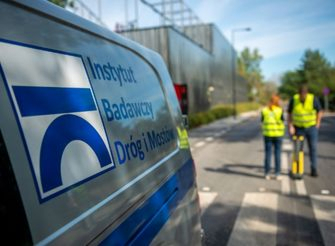
Instytut Badawczy
Dróg i Mostów
Lepsza infrastruktura, lepsze życie


O Instytucie
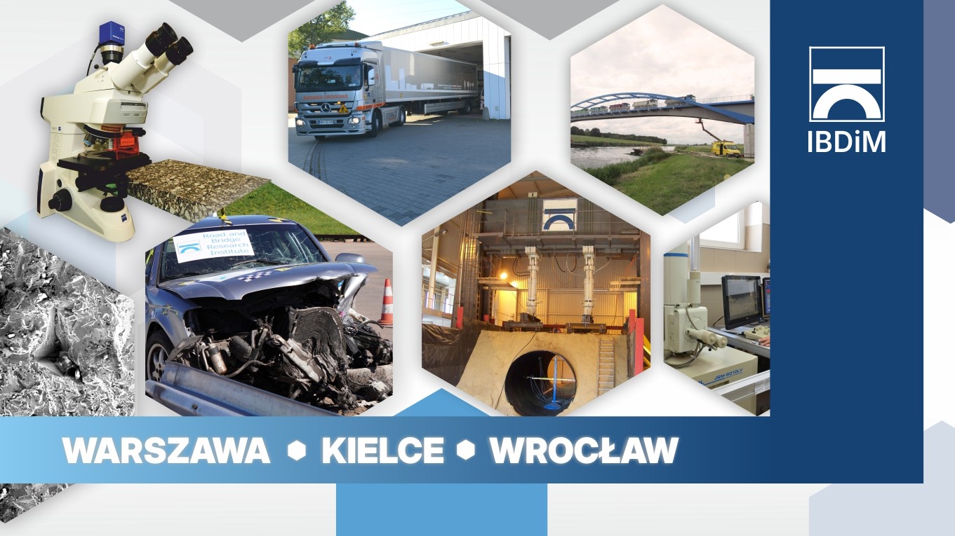
Instytut Badawczy Dróg i Mostów jest wiodącą placówką naukowo-badawczą w Polsce, która prowadzi innowacyjne badania, ekspertyzy i projekty w zakresie dróg, mostów i infrastruktury, łącząc nowoczesną naukę z praktycznymi rozwiązaniami inżynierskimi.
doświadczenia naukowego
(od 1955 roku)
zrealizowanych projektów
(krajowych i międzynarodowych)
badań i ekspertyz
(w laboratoriach i w terenie)
konferencji, seminariów, szkoleń
(stacjonarnie i online)
Najbliższe wydarzenia
Aktualności
 17.06.2026
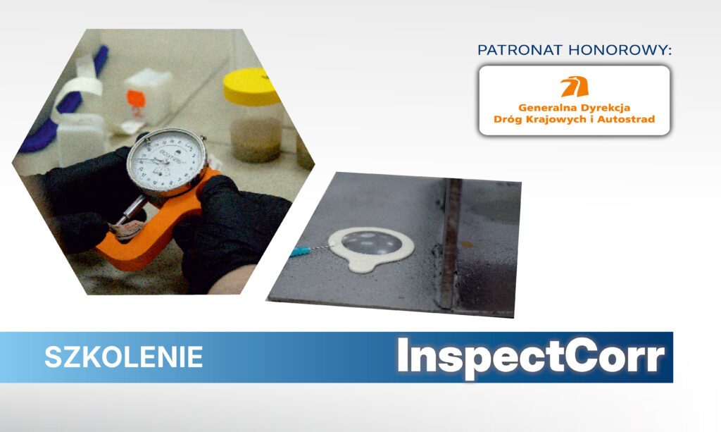 17.06.2026
 17.06.2026
o instytucie
Instytut Badawczy Dróg i Mostów jest wiodącą placówką naukowo-badawczą w Polsce, prowadzącą innowacyjne badania, ekspertyzy i projekty w zakresie dróg, mostów i infrastruktury, łącząc nowoczesną naukę z praktycznymi rozwiązaniami inżynierskimi.
przeprowadzonych badań i ekspertyz
(w laboratoriach i w terenie)
Konferencji, seminariów, szkoleń
(stacjonarnie i online)
doświadczenia naukowego
(od 1955 r.)
zrealizowanych projektów
(krajowych i międzynarodowych)
działalności badawczej
(od 1955 r.)
działalności badawczej
(od 1955 r.)
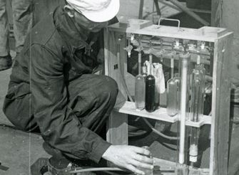
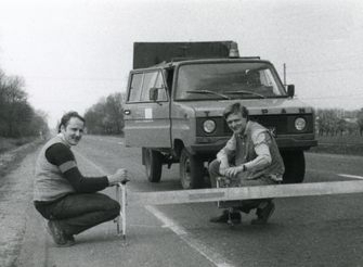
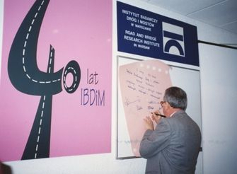
Ponad siedem dekad badań i rozwoju
Od 1955 roku Instytut Badawczy Dróg i Mostów wspiera rozwój infrastruktury transportowej, łącząc badania naukowe z praktyką inżynierską i potrzebami administracji publicznej.
Lata 60. XX wieku
Lata 80. XX wieku
Lata 90. XX wieku
XXI wiek
Usługi
Ocena i certyfikacja wyrobów budowlanych
Instytut Badawczy Dróg i Mostów prowadzi kompleksową ocenę właściwości użytkowych oraz akredytowaną certyfikację wyrobów budowlanych. Zapewniamy rzetelną weryfikację zgodności z wymaganiami technicznymi i prawnymi, wspierając producentów w bezpiecznym wprowadzaniu wyrobów na rynek krajowy i europejski.
Działalności badawczej
(od 1955 r.)
zrealizowanych projektów
(krajowych i międzynarodowych)
badań i ekspertyz
(w laboratoriach i w terenie)
Konferencji, seminariów, szkoleń
(stacjonarnie i online)
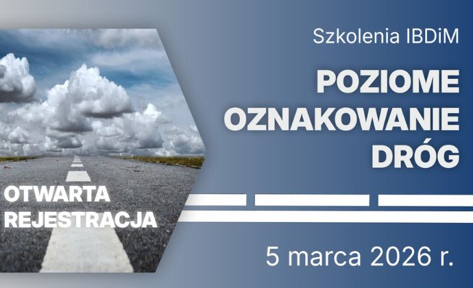
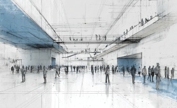
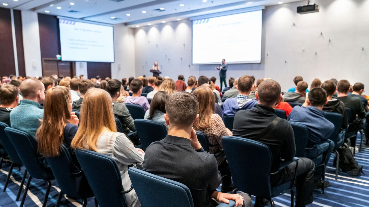
Wydarzenia
Konferencje,
seminaria i szkolenia
Instytut Badawczy Dróg i Mostów organizuje konferencje, seminaria naukowe oraz kursy i szkolenia, stanowiące istotny element działalności badawczej i eksperckiej. Wydarzenia te służą upowszechnianiu wyników badań, wymianie wiedzy oraz wspieraniu praktyki inżynierskiej w obszarze infrastruktury transportowej.
Wydarzenia
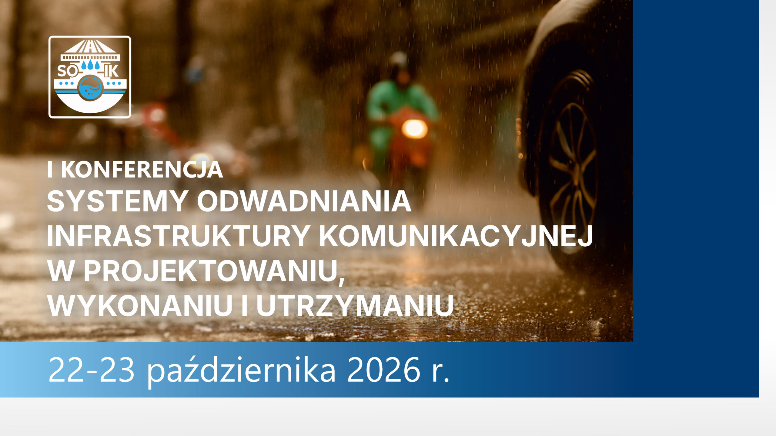
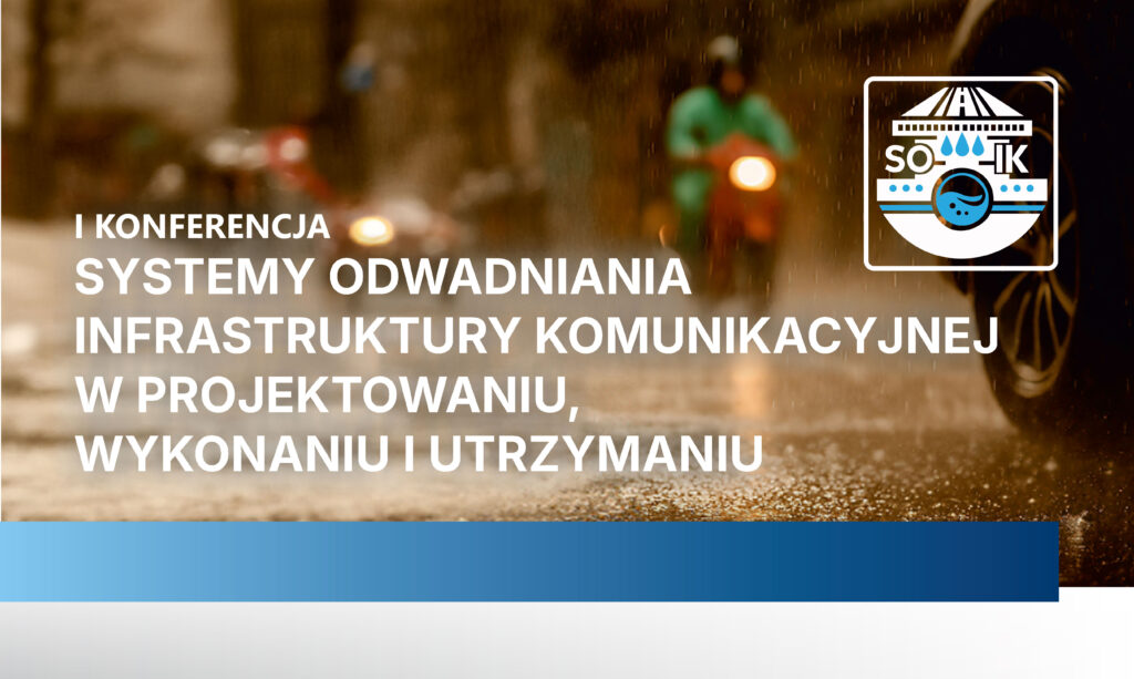
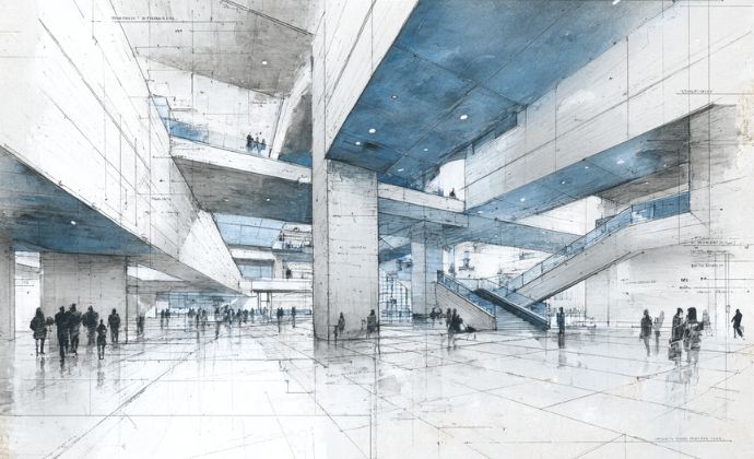
Konferencje
Konferencje organizowane przez nas stanowią platformę wymiany wiedzy i doświadczeń dla ekspertów, inżynierów i naukowców. Prezentujemy najnowsze badania, innowacyjne technologie oraz sprawdzone rozwiązania, wspierając profesjonalny rozwój uczestników i podnosząc standardy badań, projektowania i utrzymania infrastruktury.
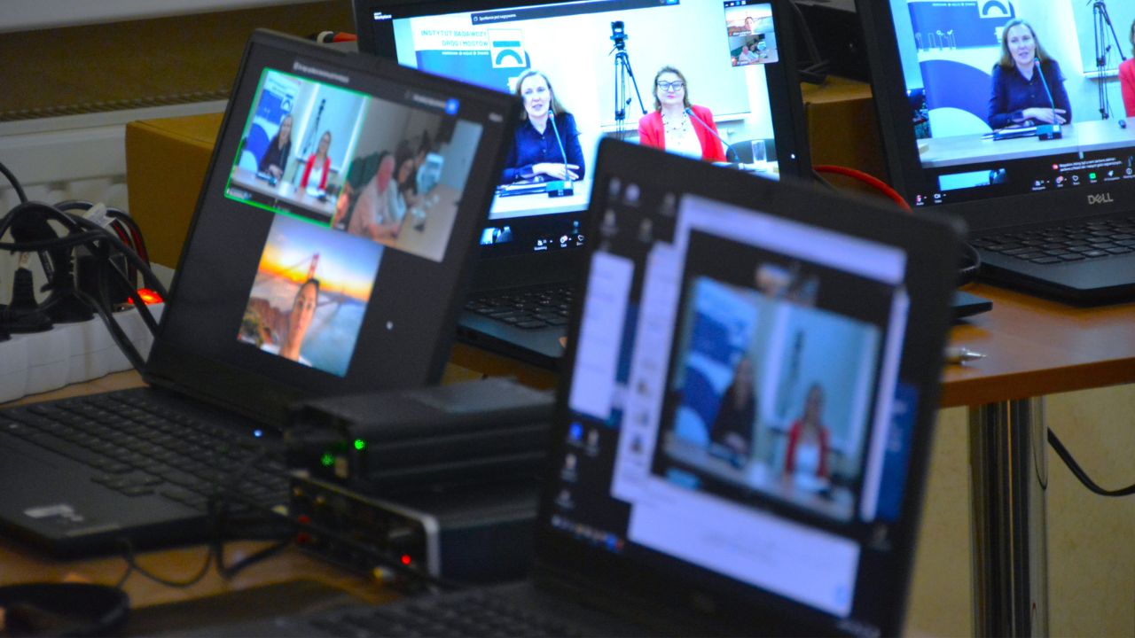
Wydarzenia
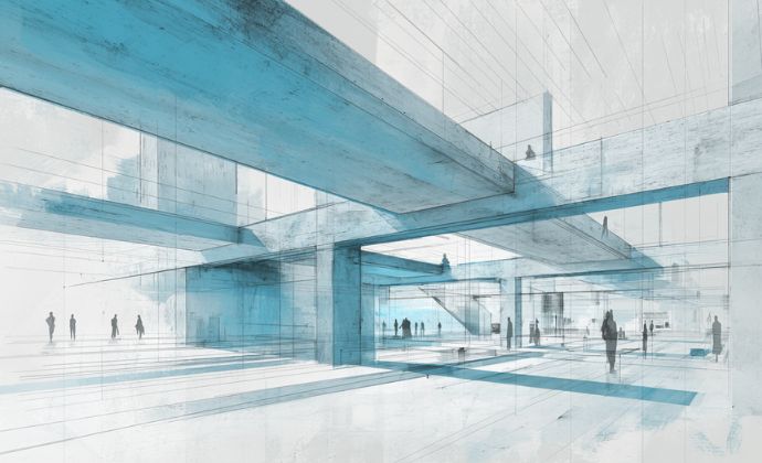
Seminaria naukowe
Seminaria naukowe organizowane przez nasz Instytut to przestrzeń wymiany wiedzy i doświadczeń dla naukowców, inżynierów i specjalistów. Uczestnicy poznają najnowsze wyniki badań, innowacyjne metody i technologie, dyskutują o wyzwaniach branży oraz zdobywają praktyczne wskazówki do wdrażania nowoczesnych rozwiązań w projektach i inwestycjach.
Wydarzenia
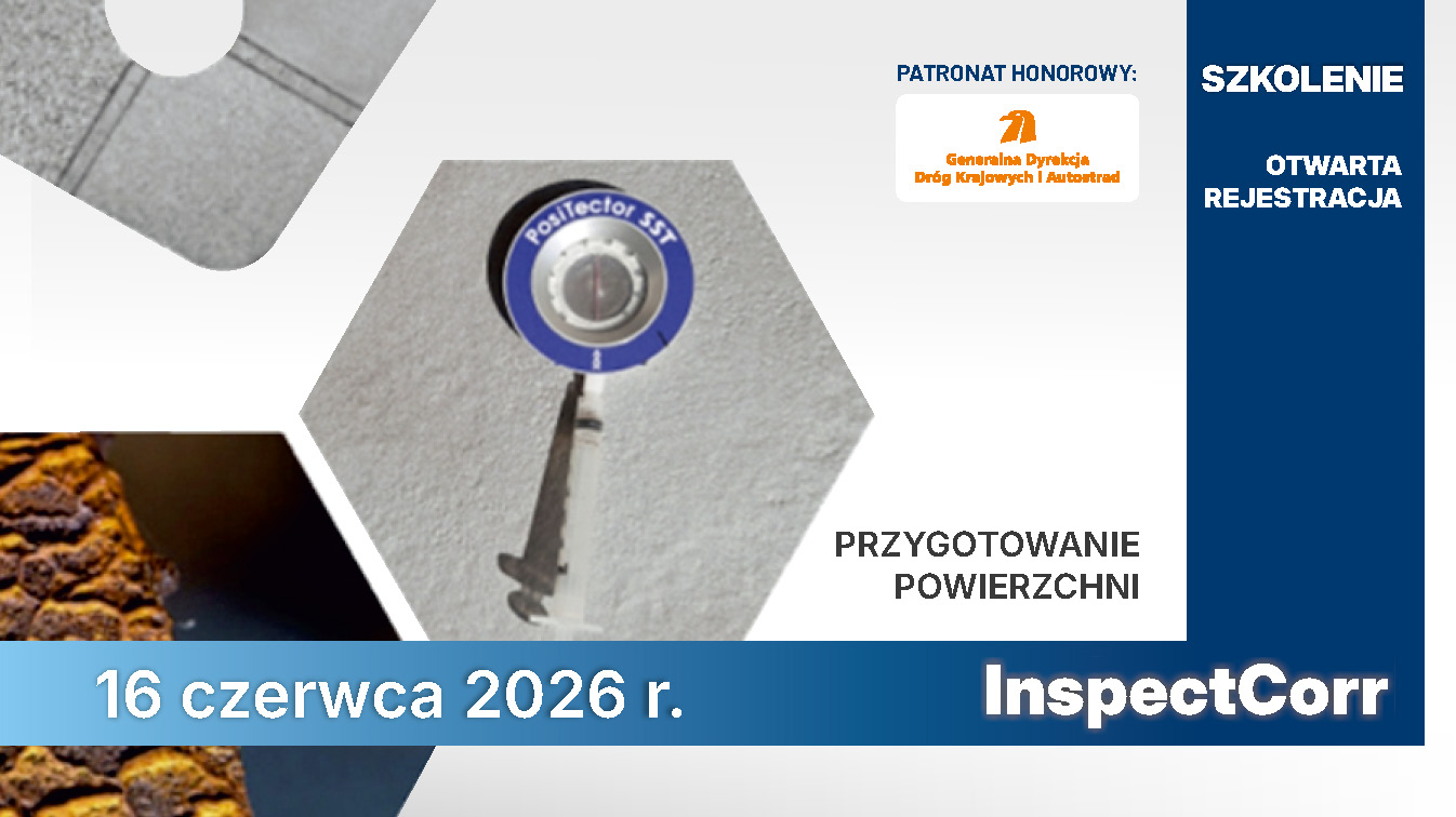
Kursy i szkolenia
Kursy i szkolenia organizowane przez Instytut łączą teorię z praktyką, umożliwiając uczestnikom zdobycie aktualnej wiedzy z zakresu drogownictwa, mostownictwa, inżynierii transportu i zabezpieczeń antykorozyjnych. Eksperci prezentują nowoczesne technologie, metody ochrony konstrukcji i praktyczne wskazówki do wdrażania innowacyjnych rozwiązań w projektach i inwestycjach.
Wydarzenia
Konferencje,
seminaria i szkolenia
Instytut Badawczy Dróg i Mostów organizuje konferencje, seminaria naukowe oraz kursy i szkolenia, stanowiące istotny element działalności badawczej i eksperckiej. Wydarzenia te służą upowszechnianiu wyników badań, wymianie wiedzy oraz wspieraniu praktyki inżynierskiej w obszarze infrastruktury transportowej.
Wydarzenia
Konferencje
Konferencje organizowane przez nas stanowią platformę wymiany wiedzy i doświadczeń dla ekspertów, inżynierów i naukowców. Prezentujemy najnowsze badania, innowacyjne technologie oraz sprawdzone rozwiązania, wspierając profesjonalny rozwój uczestników i podnosząc standardy badań, projektowania i utrzymania infrastruktury.
Wydarzenia
Seminaria naukowe
Seminaria naukowe organizowane przez nasz Instytut to przestrzeń wymiany wiedzy i doświadczeń dla naukowców, inżynierów i specjalistów. Uczestnicy poznają najnowsze wyniki badań, innowacyjne metody i technologie, dyskutują o wyzwaniach branży oraz zdobywają praktyczne wskazówki do wdrażania nowoczesnych rozwiązań w projektach i inwestycjach.

Wydarzenia
Kursy i szkolenia
Kursy i szkolenia organizowane przez Instytut łączą teorię z praktyką, umożliwiając uczestnikom zdobycie aktualnej wiedzy z zakresu drogownictwa, mostownictwa, inżynierii transportu i zabezpieczeń antykorozyjnych. Eksperci prezentują nowoczesne technologie, metody ochrony konstrukcji i praktyczne wskazówki do wdrażania innowacyjnych rozwiązań w projektach i inwestycjach.